


Please Leave Us A Message
Privacy statement: Your privacy is very important to Us. Our company promises not to disclose your personal information to any external company with out your explicit permission.
86-13597236402
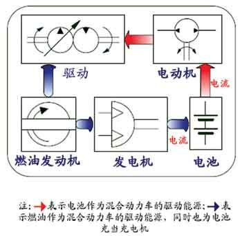
For hybrid electric vehicles, in actual operation, in order to achieve fast switching between the motor and the engine, the system is required to have a short response time; in order to ensure the stability of the vehicle operation, the system is required to have accurate current positioning; at the same time, in order to ensure The system control is reliable and accurate, and the requirements for system sampling accuracy and control speed are also high. The key to studying the energy flow control strategy of hybrid electric vehicles is to study the relationship between batteries and electric motors and engines.
This article refers to the address: http://
In practical work, the working environment of hybrid electric vehicles is complex and the influence of various interference factors is large, which brings great difficulties to the study of its energy flow state. Can I simulate and simulate the performance of a power battery in a laboratory? In this way, not only can a large amount of manpower and material resources be saved, but also a good reference for the design and assembly of the hybrid electric vehicle.
The hybrid electric vehicle energy flow simulation system described in this paper is designed to meet the above requirements. This system can simulate the actual working environment of hybrid electric vehicles and provides a flexible, simple and efficient platform for researching hybrid electric vehicle control strategies.
System Features
The whole system is built by a combined platform. According to the requirements of the simulation work, the corresponding simulation modules are combined according to the working current to form the energy control part of the whole system. This structural design can greatly reduce the size and power consumption of the entire system.
The system integrates CAN2.0B and RS-232C interface, which can communicate and exchange data with various control instruments in the car. It is compatible with the standard communication interface of the automobile master control system, and can be easily transplanted to the actual hybrid electric vehicle system. in. At the same time, it can communicate directly with the computer, and the computer can control the operation of the system, which is convenient for monitoring and simulation.
system structure
Hybrid electric vehicle energy flow simulation system mainly consists of three parts: charging system, discharge system and control system. The system structure block diagram is shown in Figure 1.
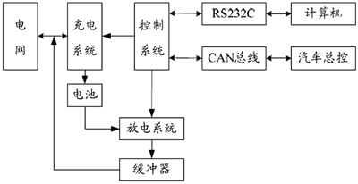
Figure 1 Simulation system structure
In the charging system, the high efficiency pulse width modulation (PWM) is adopted, and the feedback stabilization control system is adopted at the same time, so that the charging process is fast and stable.
In the discharge system, the energy-saving energy feedback method is adopted to return the electric energy to the grid or still return to the charging system to achieve the purpose of energy saving and consumption reduction.
In the control system, the high-speed embedded microprocessor is adopted, which has the characteristics of strong anti-interference ability, fast response speed and flexible control mode.
1 charging system
First, the grid voltage is rectified, pulse width modulated, and then transformed by an isolation transformer, and then rectified and stabilized to obtain the required operating voltage. In order to ensure the rapid and stable charging process, the voltage and current sampling values are introduced into the stability control system, so that the charging process is fast and stable. The structure of the charging system is shown in Figure 2.
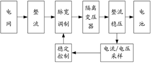
Figure 2 charging system structure
2 discharge system
The discharge system of the battery uses an energy feedback method. First, the power of the power battery is transformed, sent to the intermediate buffer, and then converted into three-phase AC by means of an inverter. This part of the energy can be used to return to the grid, and can be sent to the charging system again to realize the electric energy. Reuse, while effectively reducing the impact of current fluctuations on the grid. The structure of the discharge system is shown in Figure 3.
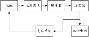
Figure 3 discharge system structure
3 control system
The system uses a high-speed embedded microprocessor-based control system. The high-speed processor can ensure the rapid completion of the charge and discharge tasks of the power battery, and the system has better anti-interference ability through digital filtering algorithm. The high-precision A/D and D/A control units make the charging and discharging process dynamic and stable, meeting the control requirements. The conversion status informs the CPU to read the conversion result in an interrupt mode to ensure a fast response of the system. The monitoring computer can control the operation of the system through the interface function, and can collect real-time parameters for data analysis, processing and monitoring. The structure of the control system is shown in Figure 4.
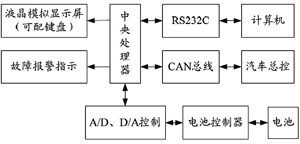
Figure 4 Control system structure
Using Microchip's PIC18F6720 as the main controller, the MCU integrates multi-channel 10-bit precision sampling converters to easily collect various signals such as battery voltage, charging current, discharge current and battery temperature. The serial communication interface can communicate asynchronously with the host computer; the SPI interface can be used to expand the internal bus; the PWM output can adjust the loop current. The control system circuit is shown in Figure 5.
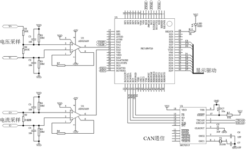
Figure 5 control system circuit
4 human interaction
The LCD display can intuitively display the working status of the system and the battery operation, and has a good human-computer interaction interface. Short-circuit and over-temperature protection, fault alarm indication are set in the control system to maximize the safety and reliability of the system and protect the safety of the system and the power battery. Figure 6 is a schematic illustration of an LCD display.
(a) working status
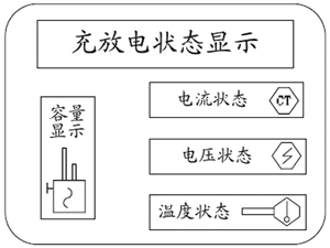
(b) Test status
Figure 6 LCD display schematic
Communication Systems
There are two communication buses built into the system: CAN2.0B and RS-232C.
1 CAN bus communication
The CAN bus is a bus serial communication technology developed to solve the data communication between various controllers, actuators, monitoring instruments and sensors in modern automobiles. However, CAN only includes the physical layer and the data link layer. The standard SAE J1939 recommended by the Society of Automotive Engineers SAE further standardizes the internal network of the car.
J1939 uses the extended frame format of CAN2.0B. The identification bits in the arbitration field of the CAN data frame are further defined. The format of the 29-bit ID is shown in Table 1.
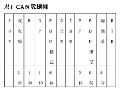
A Protocol Data Unit (PDU) consists of seven predetermined domains. They are priority, reserved bits, data pages, PDU format, PDU details, source address, and data field. The SOF, SRR, IDE, and RTR partial control fields in the CAN data frame, CRC, ACK, and EOF are not included in the PDU.
The data field is 0 to 8 bytes of data. When it is necessary to use 9 to 1785 bytes to express a parameter group, data communication will be completed by multiple CAN data frames.
2 RS-232C communication
The RS-232C is used to communicate data and control commands with the monitoring computer, perform corresponding actions according to the control commands of the monitoring computer, and transmit the state parameters of the system to the monitoring computer system.
The monitoring computer communicates with the simulation system using a query method. The data format is divided into three parts: data header, data body and check code. The data header is used to judge the category of the information, so that the corresponding processing is performed after receiving the data information; the data body stores the data information to be actually transmitted; the parity code uses the parity check code to verify the entire data. In the system, "@" is uniformly used as the beginning of transmission data, and ":" is used as the end of transmission data, as shown in Table 2.
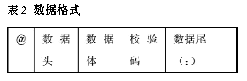
For the command information, only the header and the check code are included, and for the data information, the data body portion is also included. During the communication between the upper and lower computers, the data sender will repeatedly send the same data in the same time interval until the response message of the other party is received; if the response message is not received within a certain time interval, it indicates that a communication failure occurs. Data transmission failed. After receiving the data, the receiver will judge whether the data is complete and correct based on the data header, data tail and check code. If yes, reply to the response message indicating successful reception, otherwise wait for the sender to continue to send.
If a piece of data is divided into multiple transmissions, the transmission-response mode is adopted, that is, the next data is transmitted every time the response message is received.
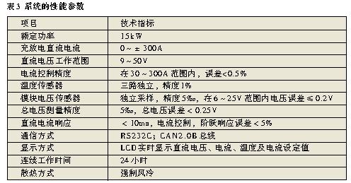
System performance indicator
Hybrid electric vehicle energy flow simulation system provides a hardware platform for researching hybrid electric vehicles, which is suitable for high-power power battery systems such as lead acid, nickel-metal hydride and lithium ion. The system displays real-time important parameters such as battery charge and discharge status, engine working status and energy flow status.
The performance parameters of the system are shown in Table 3.
in conclusion
The system minimizes the preliminary research and development investment of hybrid electric vehicles, and better solves the problems of complex modeling, low accuracy and difficulty in practical use in software simulation. According to the working state of the simulation system, the control effect can be verified to adjust the control strategy and control parameters of the hybrid electric vehicle, which provides an effective means for the design, performance prediction and analysis of the hybrid vehicle.

May 12, 2023

November 29, 2022
China's new energy vehicle charging operation and construction seminar held in Beijing recently. At the seminar, the smart electric charging system of EV group introduced by Teledin New Energy...
(1) high-voltage power distribution system: modern high-rise buildings are using two independent 10kV power supply. General high-pressure single-bus segment, automatic switching, mutual backup. The...
Recently, "Electric Vehicle Group Smart Charging System Qingdao Science and Technology Achievement Evaluation and New Energy Vehicle Charging System Construction Seminar" was held in...
1 Power Operation Power Monitoring System Introduction Power operating power monitoring system is generated with the automation of power system. The system can monitor the parameters of AC power...
Email to this supplier
May 12, 2023
November 29, 2022
Privacy statement: Your privacy is very important to Us. Our company promises not to disclose your personal information to any external company with out your explicit permission.
Fill in more information so that we can get in touch with you faster
Privacy statement: Your privacy is very important to Us. Our company promises not to disclose your personal information to any external company with out your explicit permission.