


Please Leave Us A Message
Privacy statement: Your privacy is very important to Us. Our company promises not to disclose your personal information to any external company with out your explicit permission.
86-13597236402
With the increasing popularity of battery-powered consumer electronics such as portable media players, smartphones and tablets, homes are filled with a large number of different chargers and bundles of wires. The concept of charging devices wirelessly, without any direct connection, has been around for a while, and is now quickly bringing people's interest to make it more flexible and useful. But what are the different technologies and engineers that need to cope with the design challenges?
There is a lot of attraction for wireless charging consumer devices because there is no need to use a charging cable. Perhaps it should be more clear that the purpose of wireless charging is to provide a new way to charge the device's battery through innovative ways other than wired or connector.
Wireless charging methods have become very popular in many consumer devices such as electric toothbrushes. One of the most important methods is Maxwell's law-based sensing method, in which the change of the magnetic field from one coil is generated in another coil coupled with it. Current. While the use of magnetic field sensing methods is suitable for many small devices like the above, the use of this approach in more modern consumer electronics devices such as tablets and smartphones faces many engineering design challenges.
As the power fed to the battery increases, the relative efficiency or flexibility requirements for placing the coupled coils will also increase. The primary consideration for this sensing method is how to control the electromagnetic interference (EMI) generated by the signal that generates or "transmits" the energy and transmits it to the "receiving" device using the induced magnetic field. The receiving device then converts the magnetic field energy into electrical energy to charge the battery. Wi-Fi, Bluetooth, Near Field Communication (NFC), cellular systems, and FM radio are some of the many wireless voice and data connection methods that may be subject to this electromagnetic field.
Of course, another consideration is to make the power transfer efficiency as high as possible, even under challenging constraints such as higher power levels and wider placement errors. In the past few years, the industry has put forward many new ideas on how to implement inductive charging technology, but the progress of evading the impact of EMI is not as smooth as expected, because EMI compatibility requires a lot of hard work.
The recent challenges in this area have been further developed thanks to the tireless efforts of the Wireless Charging Alliance (WPC). WPC is an action plan of the Consumer Electronics (CEA) organization to encourage further research and development to make wireless charging more compelling and to be favored by larger consumer groups.
Another well-known constraint of the sensing method is the need to accurately pair the charger and the charged device, which can be well described using an electric toothbrush example. There is a small tower on the charger substrate that rises from the substrate on which the toothbrush to be charged is placed. Using this method, the two coils can be perfectly matched to ensure the transmission of magnetic energy. Any slight misalignment will completely lose power transfer capability. This method of use is obviously inconvenient when using other devices such as smartphones or tablets that require slightly higher power levels. Finally, there is a problem of how to solve the heat loss. The higher the power of the charger, the greater the heat loss. This is even more of a problem for temperature-sensitive lithium-ion batteries, which are likely to create component stresses in today's highly compact consumer electronics designs.
The use of a capacitive architecture is another wireless charging method that can replace wireless charging of magnetic fields. The principle of this method is similar to Maxwell's law of electric fields. This concept has been adopted by Murata and is widely introduced into new designs. The company's approach is to use a quasi-electrostatic electric field and transfer energy through a capacitor that consists of two electrodes that are physically separate devices. The two devices are placed close to each other to form an array of capacitors and to transfer energy. Figure 1a shows the basic principle of this method.
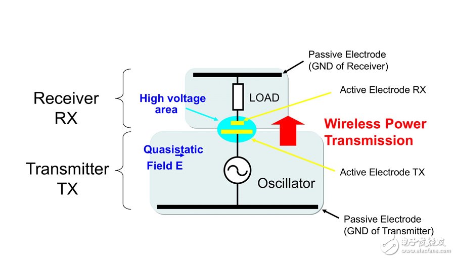
Figure 1a: Transmitter-receiver pair principle in wireless power transmission.
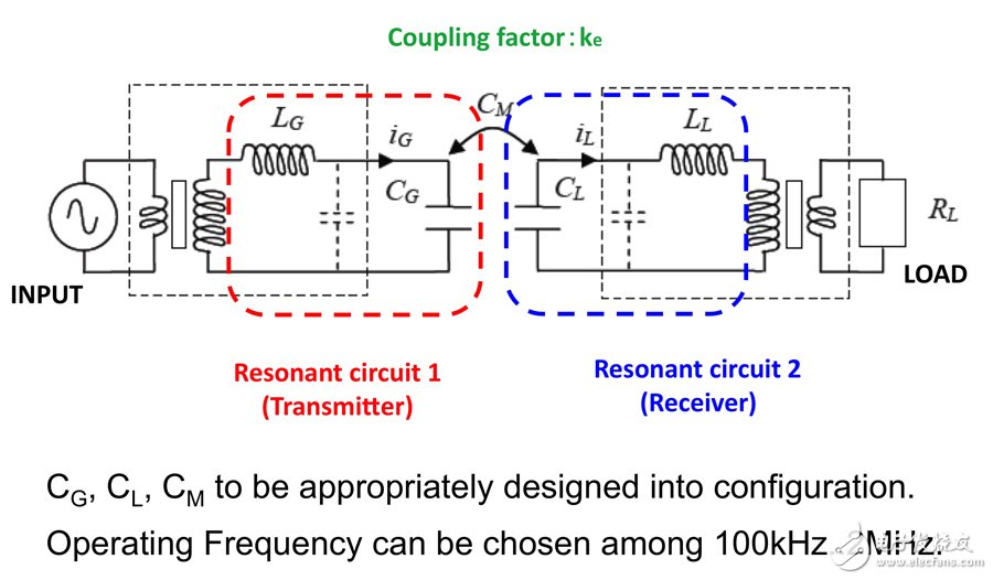
Figure 1b: Equivalent circuit of the transmitter-receiver pair shown in Figure 1a.
Energy transfer can be achieved by electrostatic induction using two sets of electrodes or plates. A charger or "transmitter" and portable device or "receiver" are used to effectively achieve longitudinal quasi-electrostatic coupling between suitably sized metal surfaces that make up the capacitor. The drive electrode or the active electrode is smaller than the other electrode, and the applied voltage is higher, and the other electrode is a passive electrode, which has a longer size and a lower voltage. Of course, under normal circumstances, the energy transmitted by the capacitor is very small, which has a great relationship with the small electrode area. Therefore, in order to meet the power level required to charge a consumer device (eg, from 5W to 25W), it is necessary to increase the electrode size and the coupled voltage value, depending on the actual configuration.
Figure 2a shows a block diagram of an example of a charger method that uses capacitors to transfer energy. The receiver and transmitter modules used are new products that Murata recently developed. This modular approach allows engineers to focus on developing the electrode design of the coupling region, which helps to quickly develop wireless charging capabilities. The amount of energy transmitted by the electrostatic method is directly proportional to the frequency used. Therefore, driving the electrode pair with a higher frequency allows the design to handle higher power. However, each country has restrictions on the frequency and electric field strength used. In fact, this configuration can form a very efficient antenna structure, so EMI factors often limit design flexibility. In order to achieve wireless transmission and reception between the coupling electrodes while minimizing the amount of external radiation, it is necessary to design correctly. Therefore, it is necessary to further understand and determine the correct electrode size, their design, operating voltage, power value, optimal operating frequency and total size constraints. In general, the ideal frequency range is between 200kHz and 1MHz, and the effective coupling region has a voltage between 800V and 1.52kV.
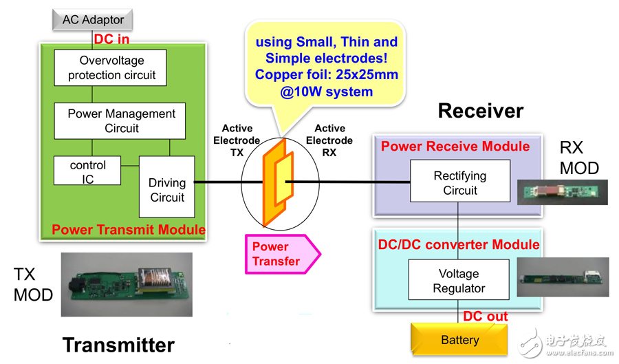
Figure 2a: Block diagram of a capacitor transfer charger.
Figure 2b shows that for a 10W charger that meets EMI compatibility requirements, there is voltage step-up and step-down in the transmit-to-receive capacitive coupling process. The design concept with a modular architecture allows device manufacturers to use the module as a black box, facilitating the integration of the transmitter and receiver. The transmitter is designed to cover the link to the power supply, control of wireless energy transfer, and control of the active coupling electrodes of any form based on positional flexibility goals. On the receiver side, the battery interface determines how the design correctly receives power from the active coupling electrode region through the downconversion module. Due to the wide variety of batteries used in portable devices, the standardized design of circuit interfaces represents a major step toward very convenient design, while also taking into account more challenging concepts such as faster charging speeds. Thanks to the continued pressure from the European Commission, the micro USB 5V charging interface is becoming the standard for all mobile phones in Europe.
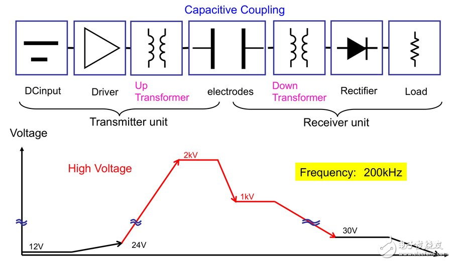
Figure 2b: Voltage step-up and step-down are part of the transmit-to-receive capacitive coupling process in a 10W charger.
One of the key advantages of using quasi-electrostatic transmission compared to inductive methods is that the location requirements of the device to be charged on the charging base (or charging tray) are less stringent. The xy (surface) direction is designed to maintain high efficiency and relatively flat curve energy transfer when the receiver is away from the source. The efficiency is typically around 80% for any design (even wired chargers). Therefore, it has very high position tolerance performance, and z (height) is still the most challenging design parameter.
In addition, the use of a flat square or rectangular tabletop tray or a nearly vertical splicing shelf allows the charging device to be placed in any orientation, without necessarily requiring precision. In addition, since the main active receiving electrode can be constructed from a simple thin copper foil (the thickness of this copper foil is on the order of a few microns, embedded in a plastic cover material), integrating it into a consumer device is more integrated than a power sensor. Much simpler.
As mentioned earlier, heat transfer close to the battery is a serious problem for the sensing method. However, the electric field as an energy carrier in a capacitively coupled configuration does not have any large current. Since there is no such DC flow, there is no heating problem in the coupling region: all resistive losses are integrated in the module or driver circuit, and the coupling region is not present at all. Device manufacturers therefore have greater design flexibility when integrating micromodules into devices, while providing significant design freedom in coupling design, power levels, and desired positioning tolerances.
With all of these challenges in mind, capacitively coupled wireless energy transfer enables higher power transfer, greater positioning flexibility, and EMC compliance, while providing manufacturers with greater design flexibility. In general, capacitively coupled wireless energy transfer will greatly encourage manufacturers to integrate the ability to wirelessly charge portable devices.

May 12, 2023

November 29, 2022
China's new energy vehicle charging operation and construction seminar held in Beijing recently. At the seminar, the smart electric charging system of EV group introduced by Teledin New Energy...
(1) high-voltage power distribution system: modern high-rise buildings are using two independent 10kV power supply. General high-pressure single-bus segment, automatic switching, mutual backup. The...
Recently, "Electric Vehicle Group Smart Charging System Qingdao Science and Technology Achievement Evaluation and New Energy Vehicle Charging System Construction Seminar" was held in...
1 Power Operation Power Monitoring System Introduction Power operating power monitoring system is generated with the automation of power system. The system can monitor the parameters of AC power...
Email to this supplier
May 12, 2023
November 29, 2022
Privacy statement: Your privacy is very important to Us. Our company promises not to disclose your personal information to any external company with out your explicit permission.
Fill in more information so that we can get in touch with you faster
Privacy statement: Your privacy is very important to Us. Our company promises not to disclose your personal information to any external company with out your explicit permission.